Advance and Retard
Advance and Retard
Many magnetos have a facility which allows the rider/driver to manually adjust the engine ignition timing while the vehicle is being used thereby catering for variations in engine load and speed so that the best performance can be obtained from the engine. This adjustment is achieved by the use of an advance/retard lever connected, sometimes by solid rod linkage, sometimes by cable, to the magneto. Moving the A/R lever rotates either the points cam (rotating armature magnetos) or the points themselves (rotating magnet magnetos) relative to the magneto drive shaft. There is often some confusion in which way the A/R lever should be moved to obtain full advance. Indicating that the lever should be pushed or pulled, turned clockwise or anticlockwise or that there should be a ‘tight wire’ or ‘slack wire’ advance is not entirely conclusive – it is necessary to check what is happening on the magneto itself. Look at these two pictures of EIC magnetos:
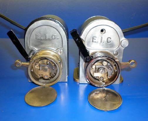
It can be seen that, on both magnetos, the points rotate anticlockwise (so they are both clockwise magnetos – see the Magneto Rotation
page in the Technical
section). Advance and retard adjustment is achieved by moving the crank arm attached to the cam ring housing but it will be immediately obvious that the position of the crank arm is different for the two magnetos - even so it is always the case that:
Full advance is achieved when the cam is rotated in the opposite direction to the direction of rotation of the points
So with these two EIC magnetos, to obtain full advance, the crank arm on the magneto on the left should be pulled up, the crank arm on the magneto on the right should be pushed down.
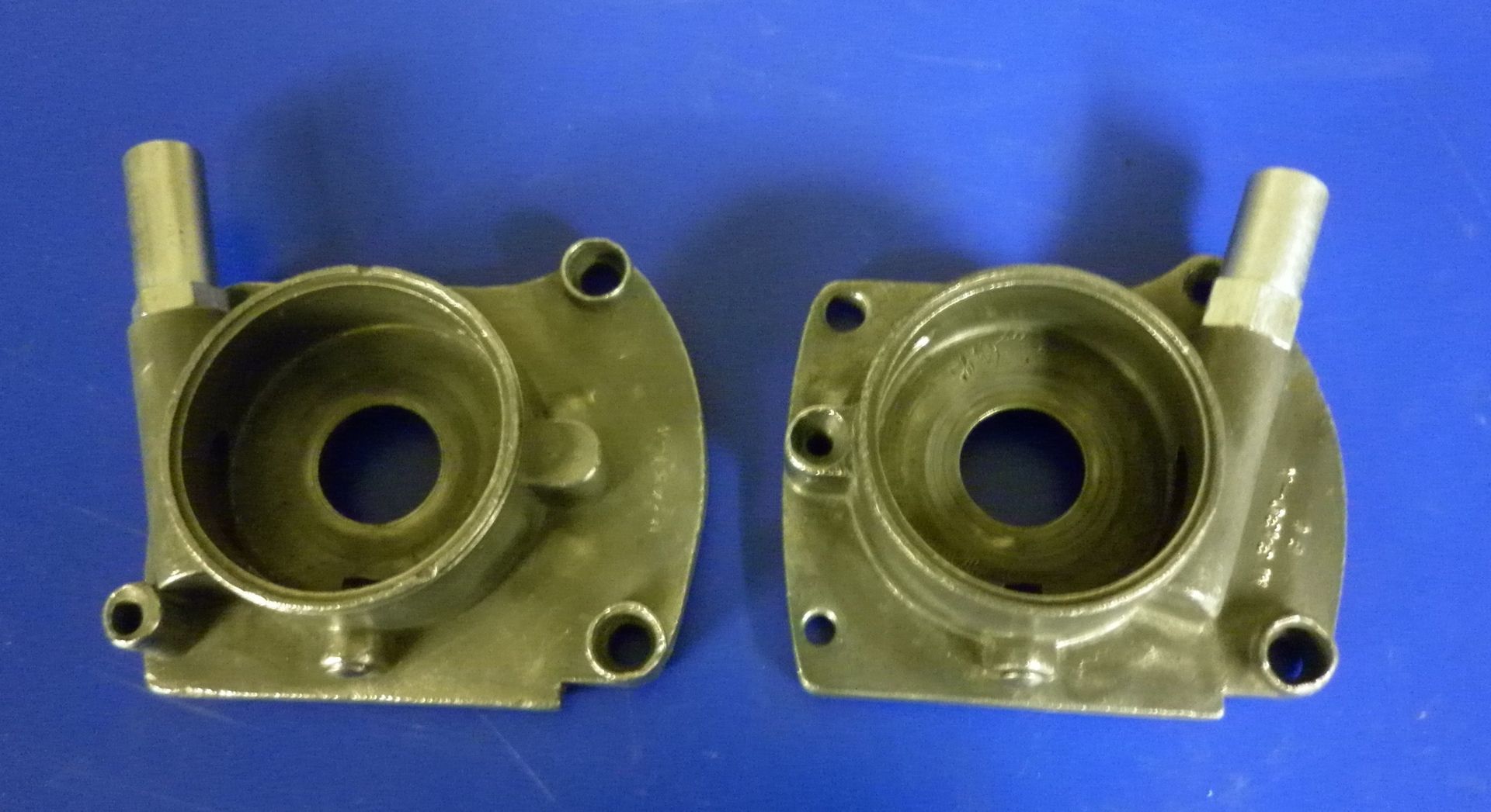
In a similar vein, this picture shows two different ends from Lucas magdynos where the face cam is moved by cable. If the assumption is made that they are both used on say, clockwise units, the one on the left would provide 'tight wire' advance where a cable is pulled, compressing a return spring, to pull the cam ring in a clockwise direction. The one on the right would provide 'slack wire' advance where the cable is released, allowing the return spring to rotate the cam ring in the same clockwise direction.
An interesting point here; note that the magdyno end shown on the left in the above picture has it's control cable on the left hand side of the points cam housing. Despite this, this part is referred to in the Lucas documentation as having a 'right hand spring' control. This can be confusing but remember that clockwise/anticlockwise direction and left/right is always referred to as seen from the drive end. So if the end is turned over so that it is viewed from the drive end, the control cable is then on the right hand side. Similarly, the end on the right with the control cable on the right is actually a left spring control!
These examples are of the rotating armature type of magnetos but the same principle applies to the rotating magnet types:
Full advance is achieved when the points plate is rotated in the opposite direction to the direction of rotation of the cam