Reversing Direction - Magnetos
Reversing Direction - Magnetos
We are often asked if the direction of a magneto can be reversed and in most cases the answer is yes, it can.
Sometimes, usually with stationary coil, rotating magnet magnetos it is just a case of re-arranging the parts already there. For instance, on some Lucas magnetos, the direction is easily reversed by pulling off the points cam and repositioning it back on the taper a little further round – there is no keyway, the cam relies on the taper to hold it in place once the locking screw has been tightened up. It is important that the cam is replaced in the correct position so that the points open just as the magnetic field is breaking down. This happens just after the edge of the armature laminations moves away from the edge of the pole piece in the magneto body.
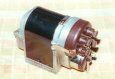
This picture of a Lucas MTT1 shows the coil removed and the rotor held in the correct position by the use of a 3/32” rod between the edge of the rotor and the edge of the body’s pole piece. The arrow on the rotor shows the required direction of rotation. With the cam placed loosely on it’s taper and without moving the rotor, the cam is rotated until the Magneto Static Timing Light indicates that the points are just opening and then locked in place.
To reverse the direction, the rod is removed and the rotor rotated back until the rod can be re-inserted on the other side of the rotor, more or less where the point of the arrow head is in the picture. Then the cam is rotated on the taper until the points are just opening as before.
This describes the general idea but check the data applicable to your particular magneto. On some magnetos (including Lucas RS types), rotors and pole pieces are not symmetrical so it is important to make sure the pin is trapped against the correct rotor edge. Also, the required pin diameter varies for different magnetos and on some it even differs for different directions of rotation! On a Lucas SR magneto for instance, the relevant Lucas Workshop Instructions data states that a 0.060” rod is needed for single cylinder, clockwise rotation, or a 0.072” rod for single cylinder and all multi-cylinder, anticlockwise rotation.
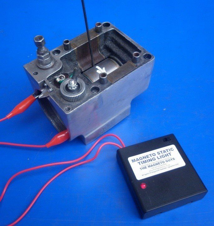
Rotating coil magnetos fitted with a ring cam usually require a change of contact breaker points if the rotation is to be reversed. This picture shows two sets of Lucas points.
The set on the left is for anticlockwise rotation, the set on the right is for clockwise rotation. Remember that the rotation is always described as looking from the drive end of the magneto - see here. Even with the correct set of points, there is still a danger that the keyway on the taper on the other side of the points plate is in the wrong position. Bosch, in particular, had a wide variety of keyway positions on what otherwise look like identical sets of points. It is possible to re-position the key if necessary.
For single cylinder magnetos, changing the points is sometimes all that is required though on some occasions the cam also needs to be changed or repositioned. The same applies to most twin cylinder magnetos but in addition, the slip ring will usually (but not always!) need to be changed as well. Twin slip rings only have a short section of brass for connecting the HT with each pickup brush in turn. That brass segment needs to be in a different position for clockwise and anticlockwise rotations. There is a picture showing the difference on the Slip Rings
page.
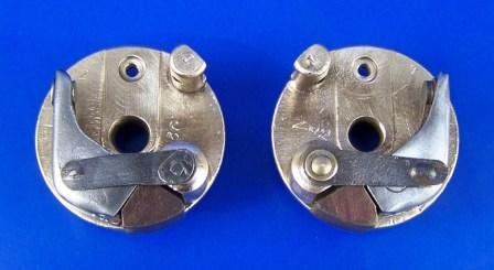
These two pictures show both sides of the same cam. The red line is the rising edge of the cam where the points open, remaining open while they cross the white section. Here, the cam is stamped L on one side and R on the other so it simply needs to be turned over to suit the required direction of rotation.
On face cam magnetos such as the Lucas magdyno and N1 models, the same points can be used when reversing direction. However, in these magnetos, the cam needs to be changed to achieve the correct internal timing. The cams are usually - but not always - marked L or R to identify the direction of rotation.

The next thing to look at are the pole pieces.
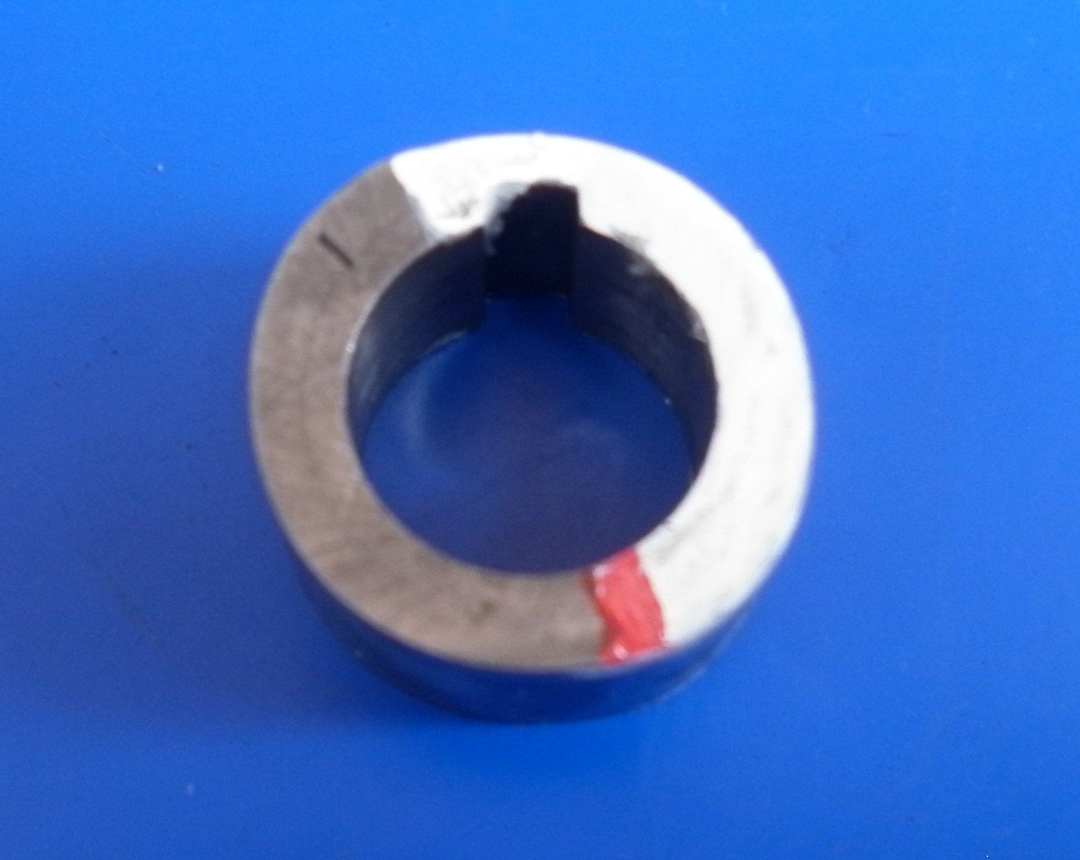
Sometimes, the two pole pieces are shaped differently as shown here on this Simms magneto. On some early horseshoe type magnetos which are simply screwed together, they can be easily swapped over but not so easy if they are cast into the body of the magneto.
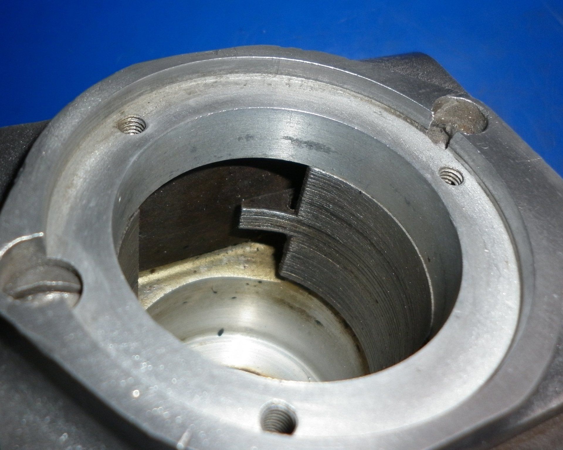
Sometimes some of the laminations are extended as shown here. This is done to improve performance of the magneto when the ignition is retarded. On these two magnetos, the armature would revolve in an anticlockwise direction as looking at the picture. On the first one, the pole pieces could be swapped over to reverse the direction. By the time the second one had been manufactured, designs had moved on and had reached the stage where the magnet and pole pieces were usually cast into the aluminium body. In these cases the direction of rotation cannot be reversed - a different body would be needed.

For all types of magnetos, the important thing to achieve is to make sure that the points start to open just as the magnetic field breaks down. It is often not possible to find this position using the rod as mentioned above because the armature/rotor is usually totally enclosed by the body.
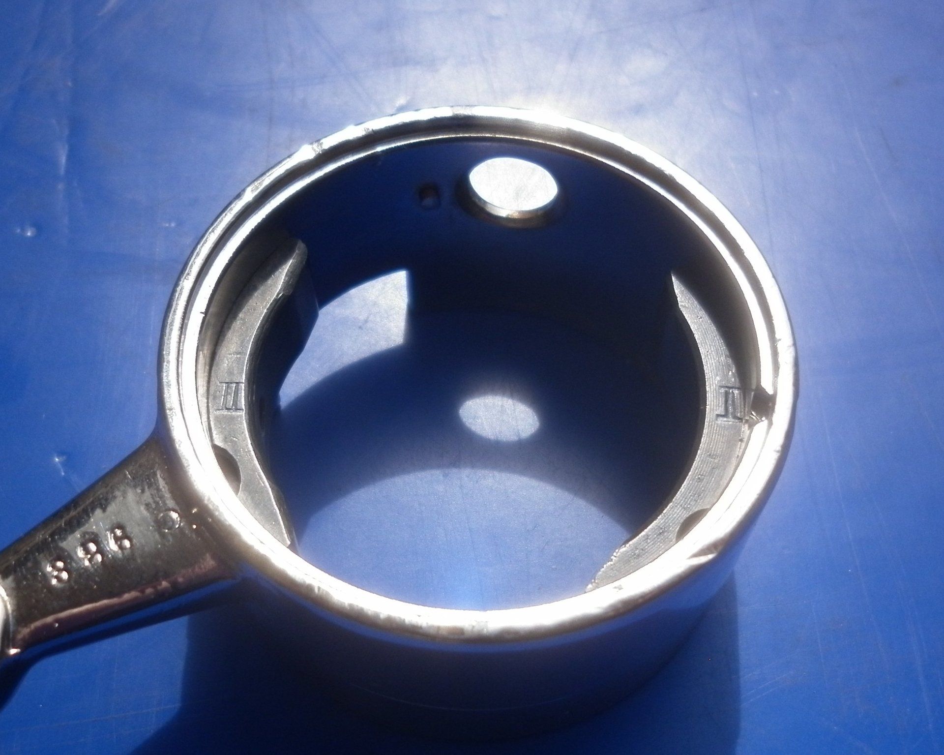
Some magnetos have an inspection plate which can be removed so that a rod can be inserted to set the correct armature/rotor position. One such example is the Eisemann RC magneto shown in this picture. With this magneto, the manufacturers indicate a 2-3mm rod should be used to position the rotor in the correct position so the shank of a 2.5mm drill is ideal.
If the magneto does not have an inspection plate, there is no alternative other than to rely on the ‘feel’ of the magnetic pull collapsing as the armature is rotated by hand.
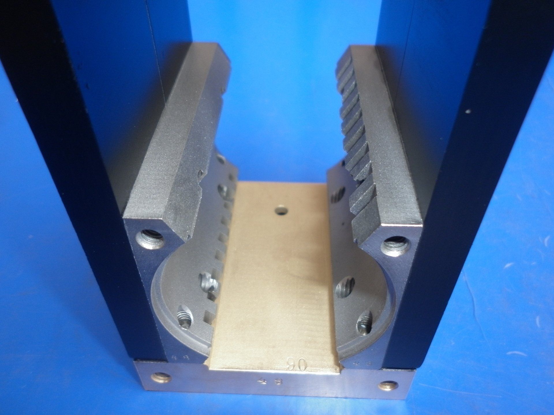
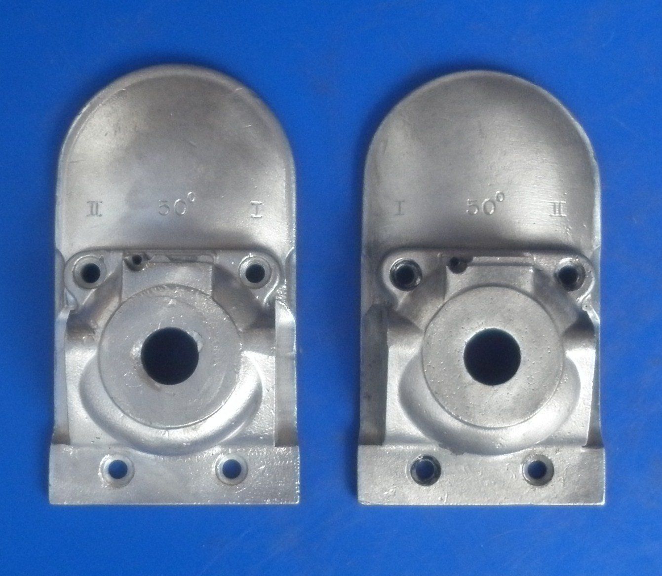
V twin magnetos are a bit more involved. When the points rotate, moving from cam 1 to cam 2 is always the larger angle, continuing round from cam 2 back to cam 1 is the smaller angle. So, applying this to the Bosch ZEV cam ring shown in the picture below, it follows that, with the larger angle at the top, the points would be going anticlockwise - so this cam ring is for a clockwise magneto. Its easy enough to swap the cams over though it is always worth checking that the angles are still correct - see here. In the second picture of the ZEV's end plates, it can be seen that the pickups are labelled I
and II
- but on opposite sides to suit clockwise and anti-clockwise rotations. This is not so easy to change!
In addition to the above, multi cylinder magnetos require one more change. The gearing between the armature and distributor rotor needs to be altered. This will involve dismantling the magneto so that the gears can be disengaged, one of them rotated to the new position, re-engaged and then everything reassembled. The gears are usually marked in some way to assist with this job.
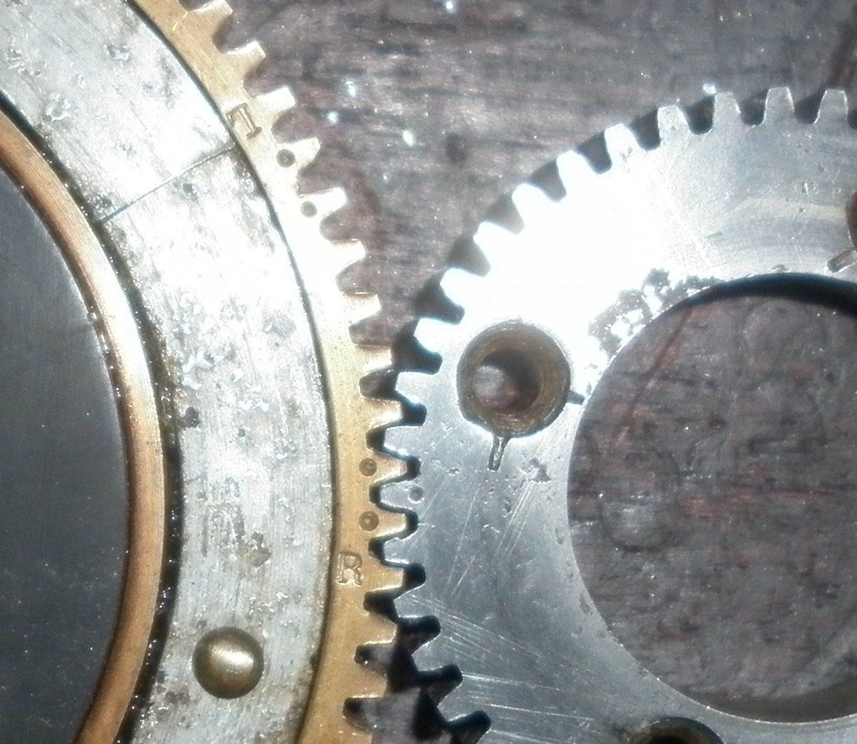
This picture shows one tooth of the steel gear marked with a single dot and the brass gear with two adjacent teeth marked with dots. Here, the gears are set up for a clockwise (Right) magneto. It can be seen that converting to anticlockwise (Left) operation, would require lifting the brass gear and rotating it clockwise half a dozen teeth.
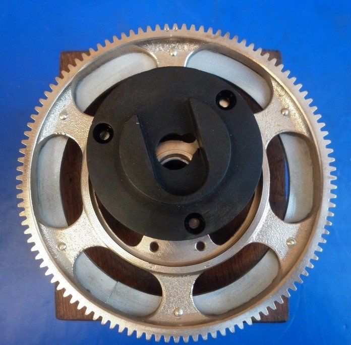
Usually only one gear needs to be moved, sometimes such as on this Simms SF4LO, both need to be rotated.
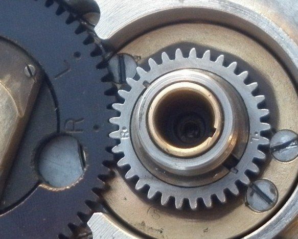
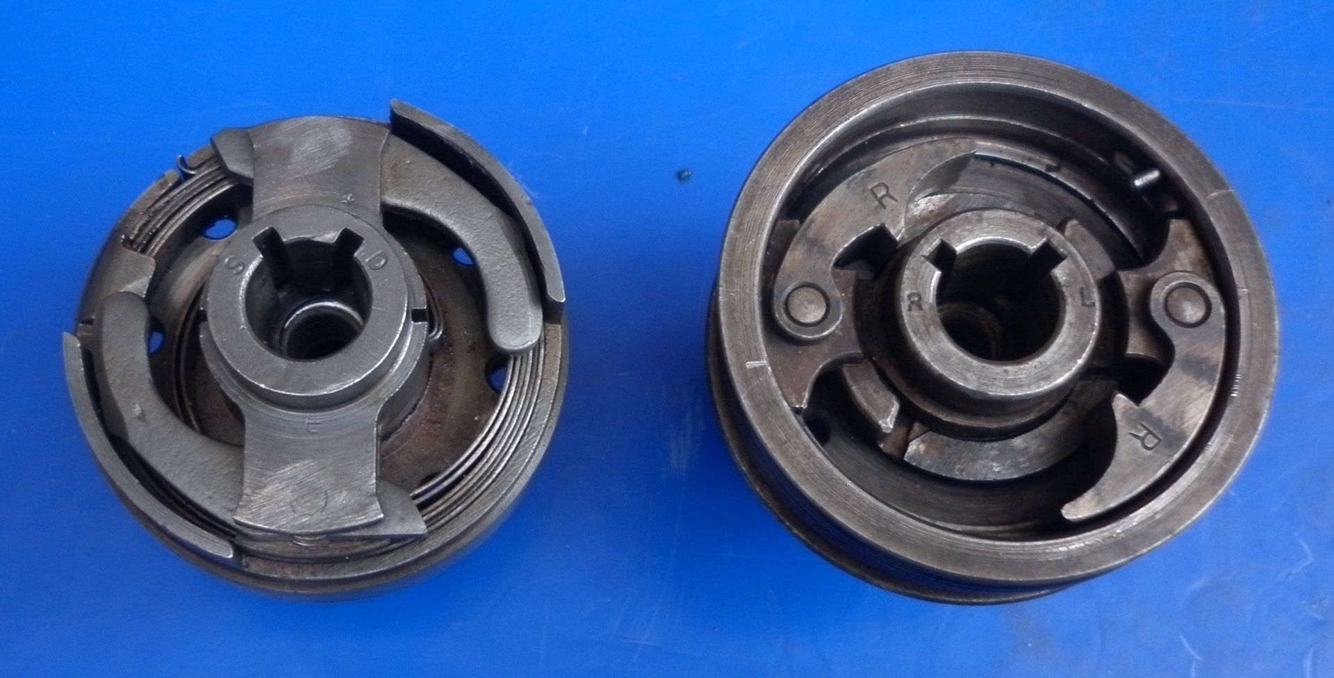
These two examples show the gears marked with R and L (Right and Left). Sometimes you will see A and C (Anticlockwise and Clockwise), French magnetos use G and D (Gauche and Droit), German Bosch magnetos use R and L (Rechts and Links), Italian Magneti Marelli magnetos use S and D (Sinistra and Destra).
On this Bosch D6 magneto, there is only one set of dots - at the 12 o'clock position. Here the gear doesn't need to be moved. Instead, the mount for the rotor arm is rotated and fixed to the gear using a different set of three holes for the three countersunk fixing screws
Even when the manufacturer’s marks are used, we sometimes find that this is not the ideal position. It is important to check the alignment between the rotor and the distributor cap. Particularly on the earlier brush type distributors, if the points open before the brush in the distributor cap is entirely on the brass segment on the rotor arm, the resulting spark between the two will burn away both the insulation and the edge of the brass on the rotor arm. If ignored, the inevitable hole will get bigger and bigger until the carbon brushes, unable to follow the uneven path, eventually break off.
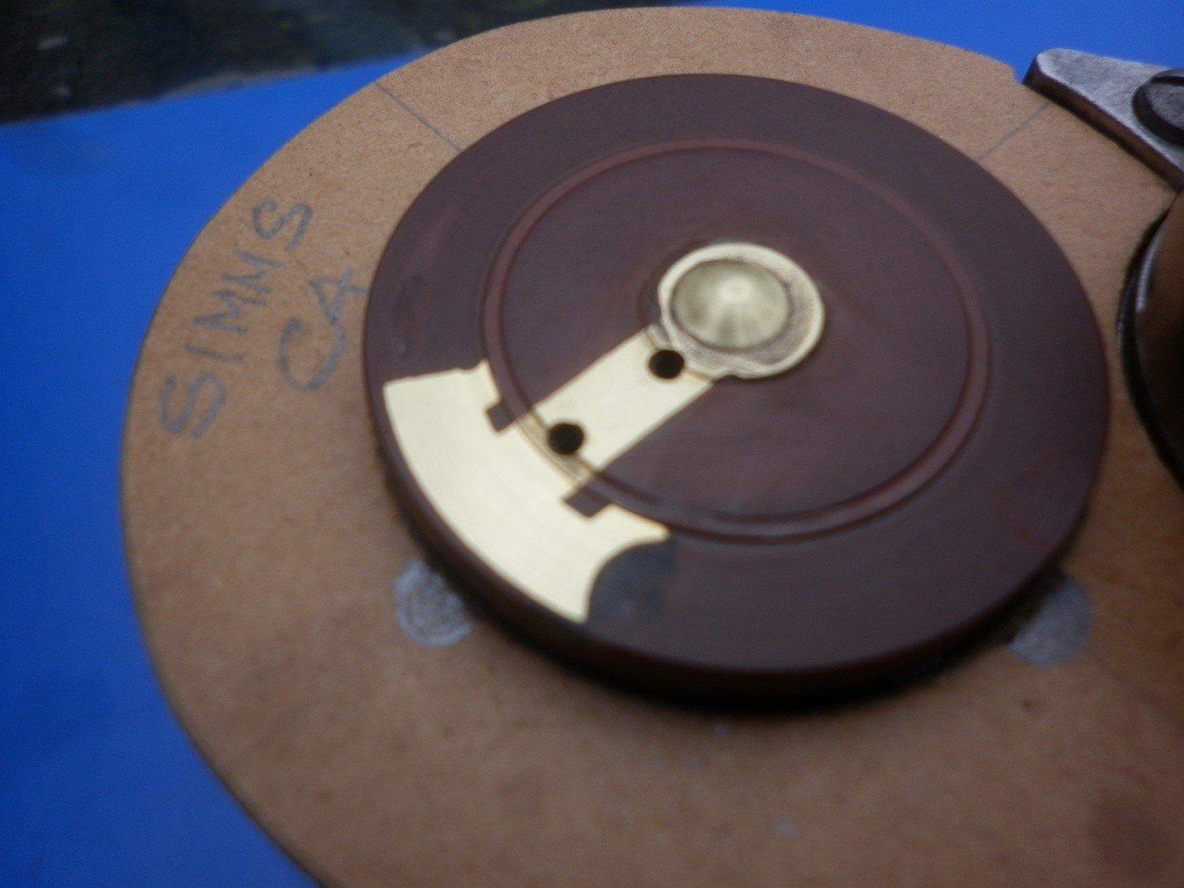
This picture shows the rotor from a Simms C4 magneto where this had happened. We repaired the rotor to give a flat surface for the brushes to slide over and reassembled the magneto by the manufacturer’s marks. We then checked the rotor/distributor contact alignment using a wooden distributor template as shown.
Note that the positions of the distributor cap brushes are pencilled in on the template.
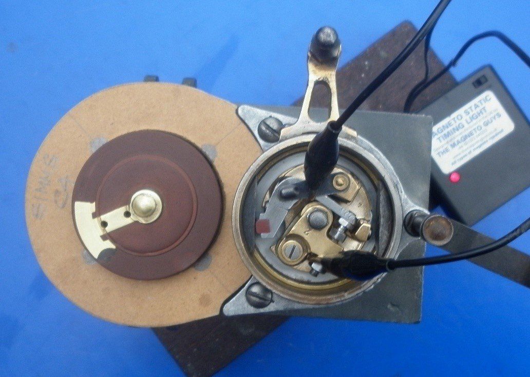
Using our Magneto Static Timing Light
to determine exactly when the points just open, this first picture shows the alignment between rotor and brush when the magneto is in the fully advanced position.
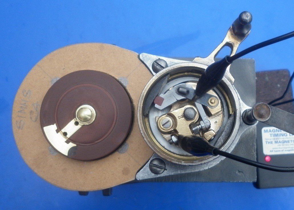
The cam ring was then rotated to the fully retarded position and alignment checked again.
It can be clearly seen that, throughout the full range of the advance and retard lever, the spark only occurs when the brush is on the first half of the brass rotor arm segment. Changing the gear meshing by one tooth moved the range of brass used to a more central position, well away from the insulation.
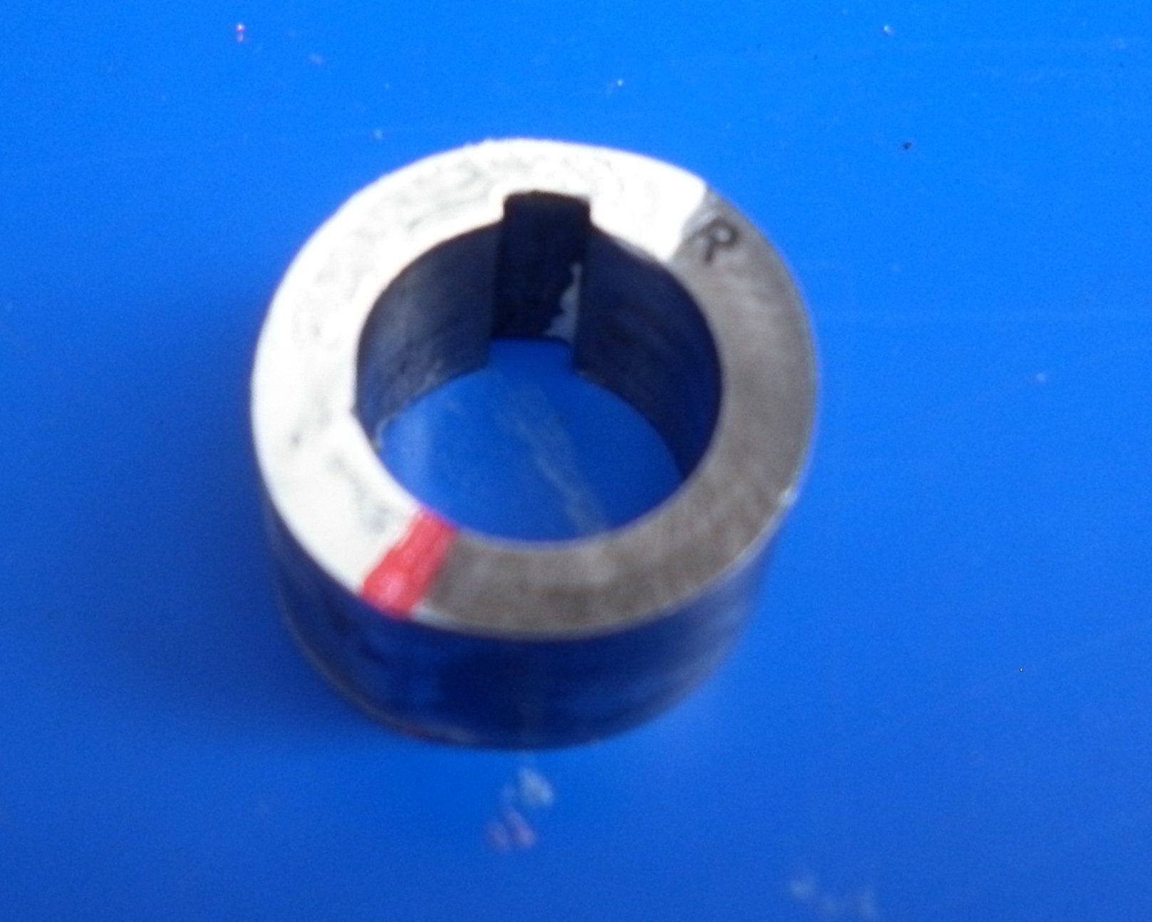
One final thing to check is the impulse starter if one is fitted. These are obviously designed to work in one direction only but again, can usually be reversed if needed. Once spinning, centrifugal force will fling the bob weights out. Consider the unit on the right in the picture below.
As viewed here, this unit needs to spin in an anticlockwise direction to fling the bob weights out. But note that the picture was taken as viewed from the magneto side - when viewed from the drive side it will need a clockwise rotation to work - hence the R on the bob weights. This unit is for a clockwise magneto so would need to be fitted using the R keyway. If the direction is to be reversed, the bob weights are simply lifted off the pivots, turned over and replaced in the opposite direction. Then the unit is fitted using the L keyway. The unit on the left also has a choice of keyways - labelled S and D this time. This one is also for a clockwise magneto but on this unit the bob weights are riveted in place so reversing the direction would be a little more involved.
IT IS VITALLY IMPORTANT TO CLEAN AND SET THE CONTACT BREAKER POINTS TO THE RECOMMENDED GAP BEFORE ANY OF THESE OPERATIONS ARE PERFORMED