Condensers - practical
Condensers - practical
This page describes how the condensers can be tested and then, if found necessary, how they are replaced. The theory of what a condenser is and why it is needed in a magneto is described on the Condensers - theory
page in the Technical
section.
We carry out three tests on magneto condensers using modern digital electronic test meters.
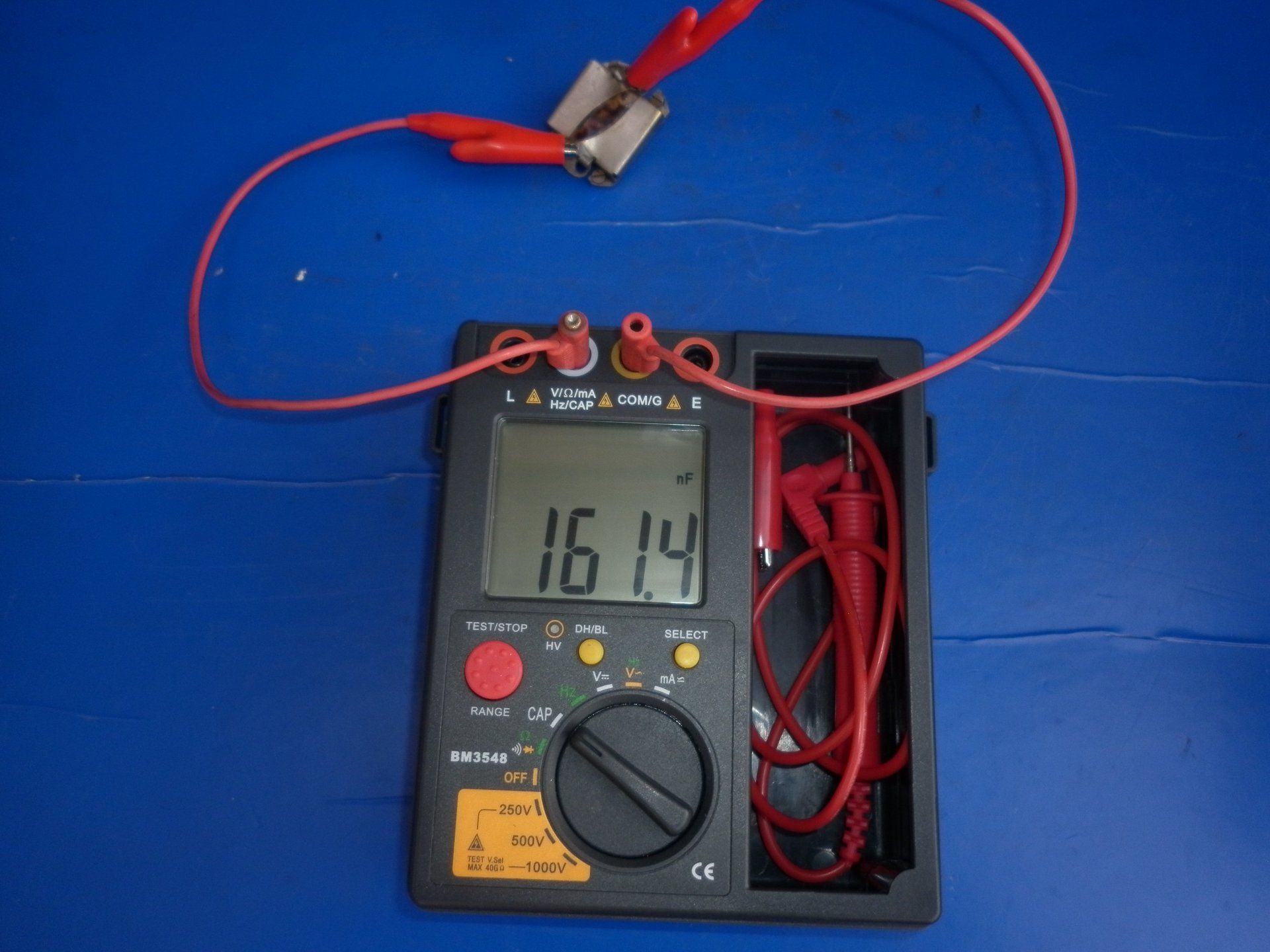
1: Capacitance test. Easily carried out using a digital capacitance meter. Expect to see a value of 100 - 250nF (that's 0.100 - 0.250 micro Farads). The lower end for small magnetos, the upper end for larger magnetos with stronger magnets. This one is reading just over 161nF so that's a good result.
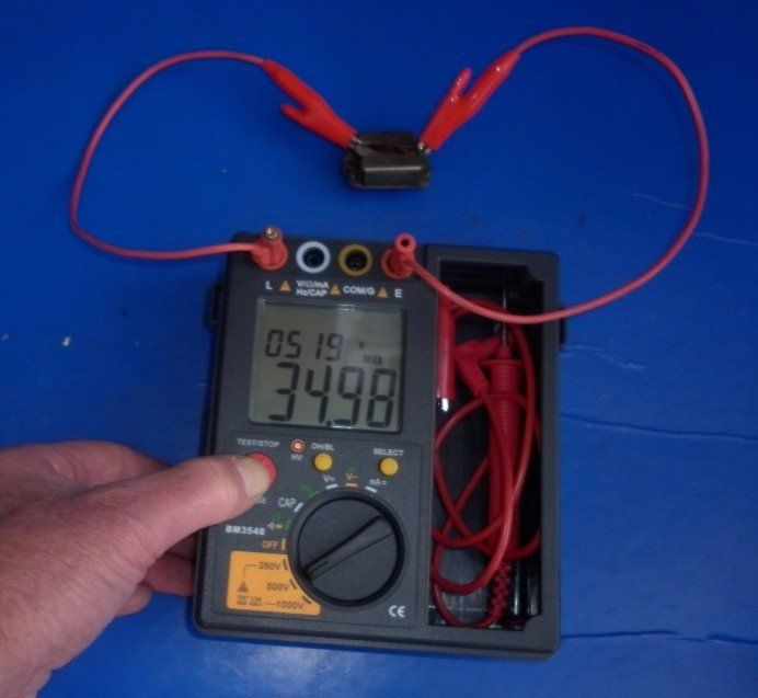
2: Insulation test. Again easily carried out using a digital insulation meter. Most have a facility to select the test voltage which should be chosen to represent the type of voltages the condenser is likely to see in normal operation. On this one, 250v would be a little low. It's probably not wise to use the 1000v range. It is too high and will only serve to over stress the condenser and may damage an otherwise usable component. We use the 500v range. You should expect to see in excess of 10Mohms. This one is reading a shade under 35Mohms so that's a good result too. When the 'test' button is released, the meter automatically discharges the condenser so that it is safe to handle.
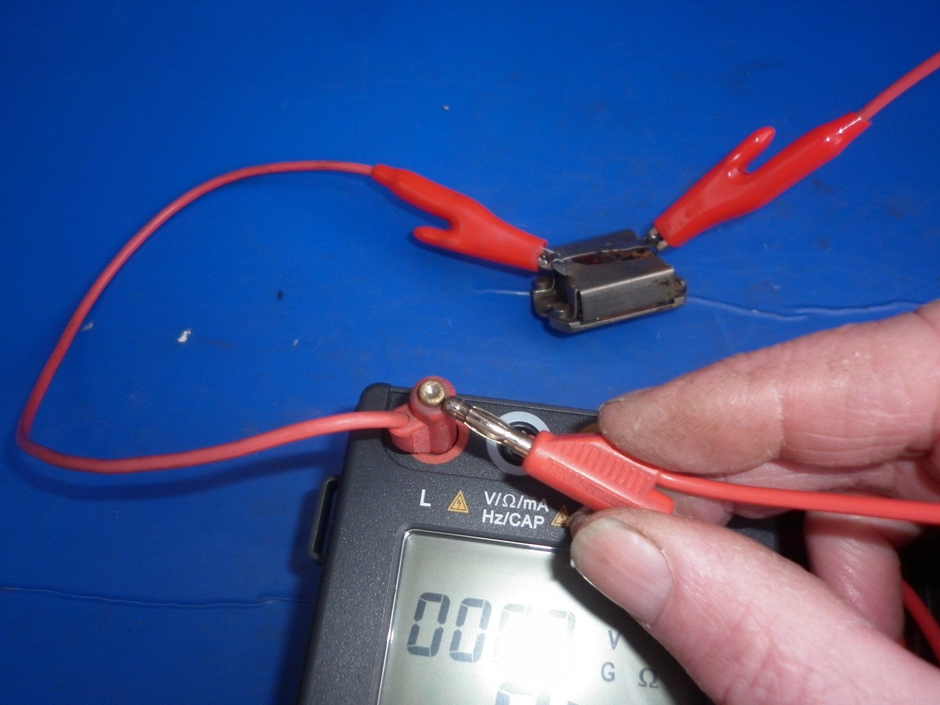
3: Charge test. This follows on from the insulation test. Press the ‘test’ button again to apply 500v to the condenser. Keep the button pressed down while one of the leads is removed from the meter. Do this very carefully as the condenser will be charged up. Count six or seven seconds and then touch the free lead on the other one to short the condenser - made easier by fitting a brass extension on the test lead left in the meter as shown. There should be a noticeable ‘crack’ heard and a spark seen as the condenser discharges. If they are not present, then the condenser has lost it’s charge through internal insulation leakage and should be replaced.
If the capacitor passes these tests, it only indicates that it might
be alright. The condenser will get hot when in normal use so we put it in the oven for an hour at about 60-70°C and test again. This is because the insulation properties do deteriorate as the temperature goes up.
The mica condensers, although up to a hundred years old, more often than not, test out OK. If they need to be replaced, it is usually because of physical damage rather than a loss of electrical performance.
As for the paper condensers, well to be honest we used to get so many failures when testing that we don’t even bother now – we always replace them with new ones. Even NOS (new old stock) ones fail.
CAUTION:
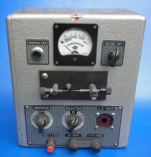
Sometimes vintage test equipment becomes available but be careful. We found this combined coil and condenser tester on a stall at an autojumble - couldn't resist it. When first used to 'test' an old condenser, it indicated a 'pass' which was a bit surprising as we had already rejected it folowing our usual tests. Further examination showed that the tester only used 60v to test the insulation. That's way below what the condenser would see in normal operation. If you have any old test equipment which gives a 'pass' or 'fail' result, it is important to check just what test parameters are used.
As for our autojumble 'bargain', we now have a nice looking ornament and a good conversation piece but it's not much use for anything else!
Replacing condensers
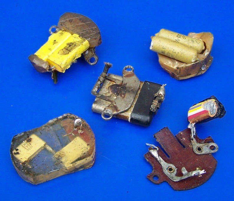
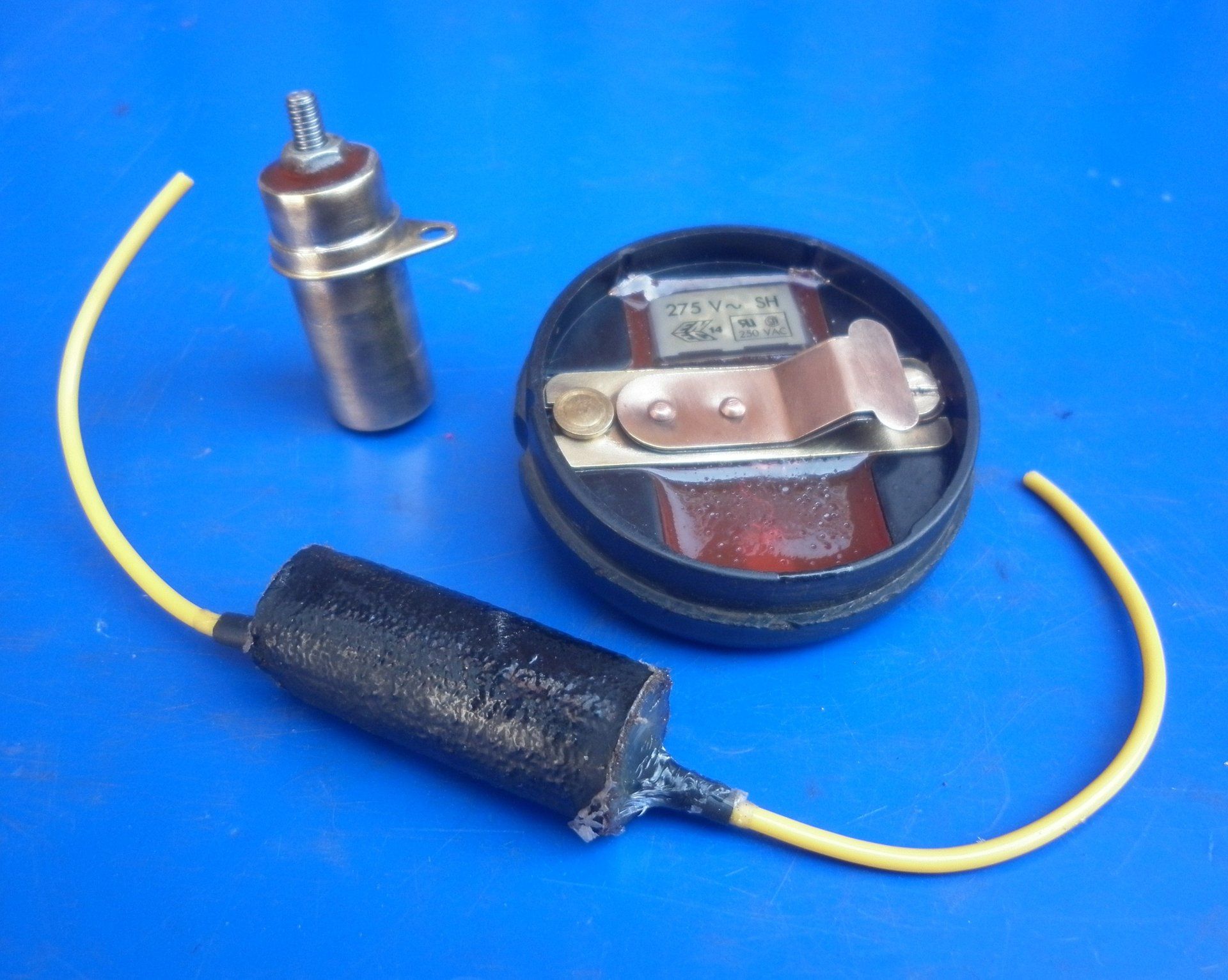
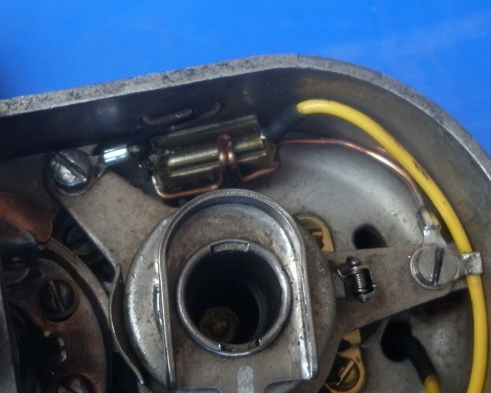
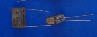
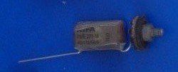
There are many different capacitors available. Some are suitable for use in magnetos, many are not. This picture shows some which have been installed by others and which have failed. The Magneto Guys always fit EVOX RIFA 271M capacitors as replacements in the magnetos we overhaul - the
Condensers - theory page in the
Technical section explains why. We would be the first to admit that these are not the only suitable replacements. Yes, other alternatives are available but we use the EVOX RIFA capacitors because experience over many years, with them fitted in thousands of magnetos convince us that these work well - we have had no electrical failures with them at all. So we stick with what we know works and see no need to experiment with any new options which come on the market.
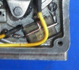
We fit the EVOX RIFA condenser in a variety of ways. When used in the end of an armature, it is held in place with a resin compound.
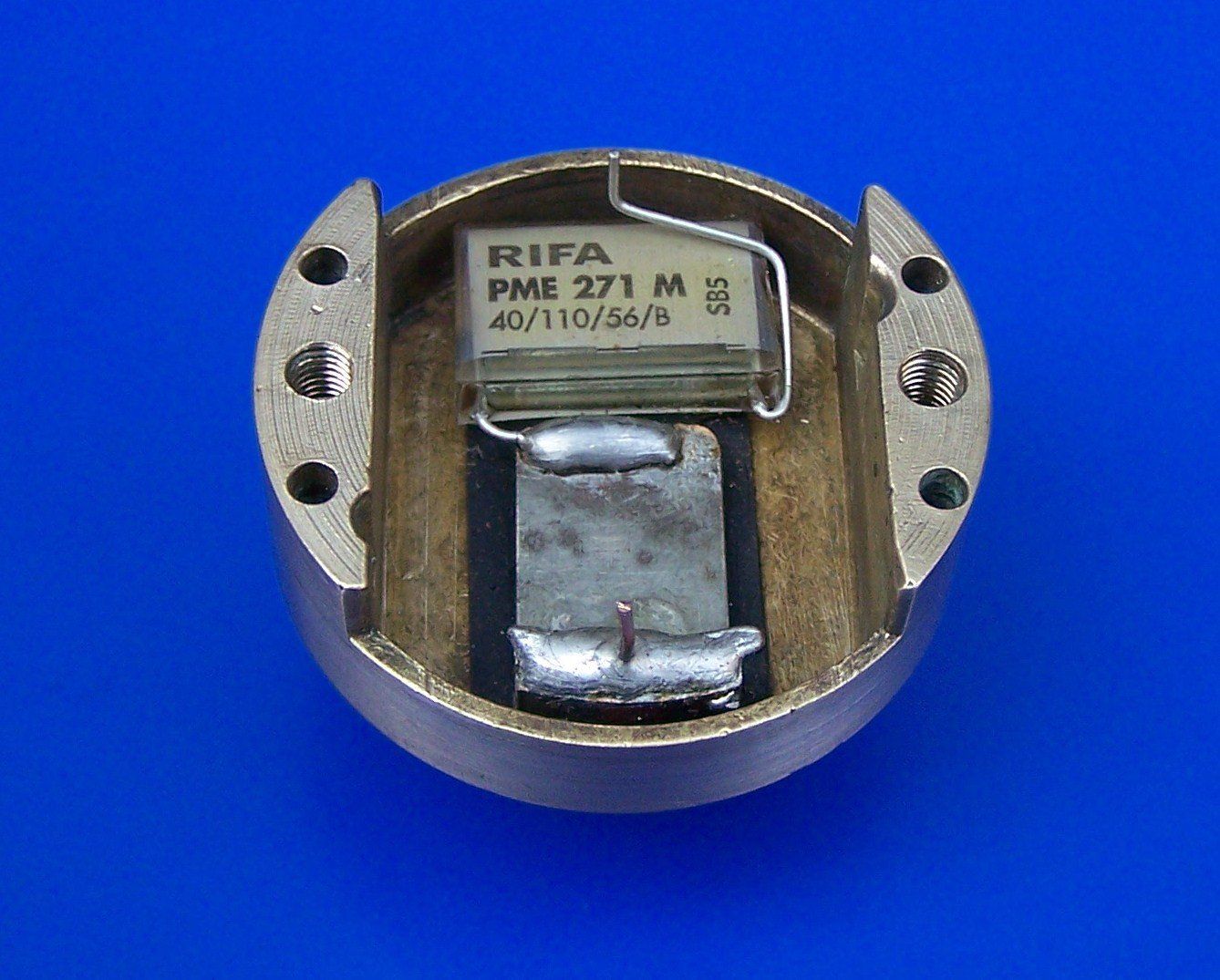
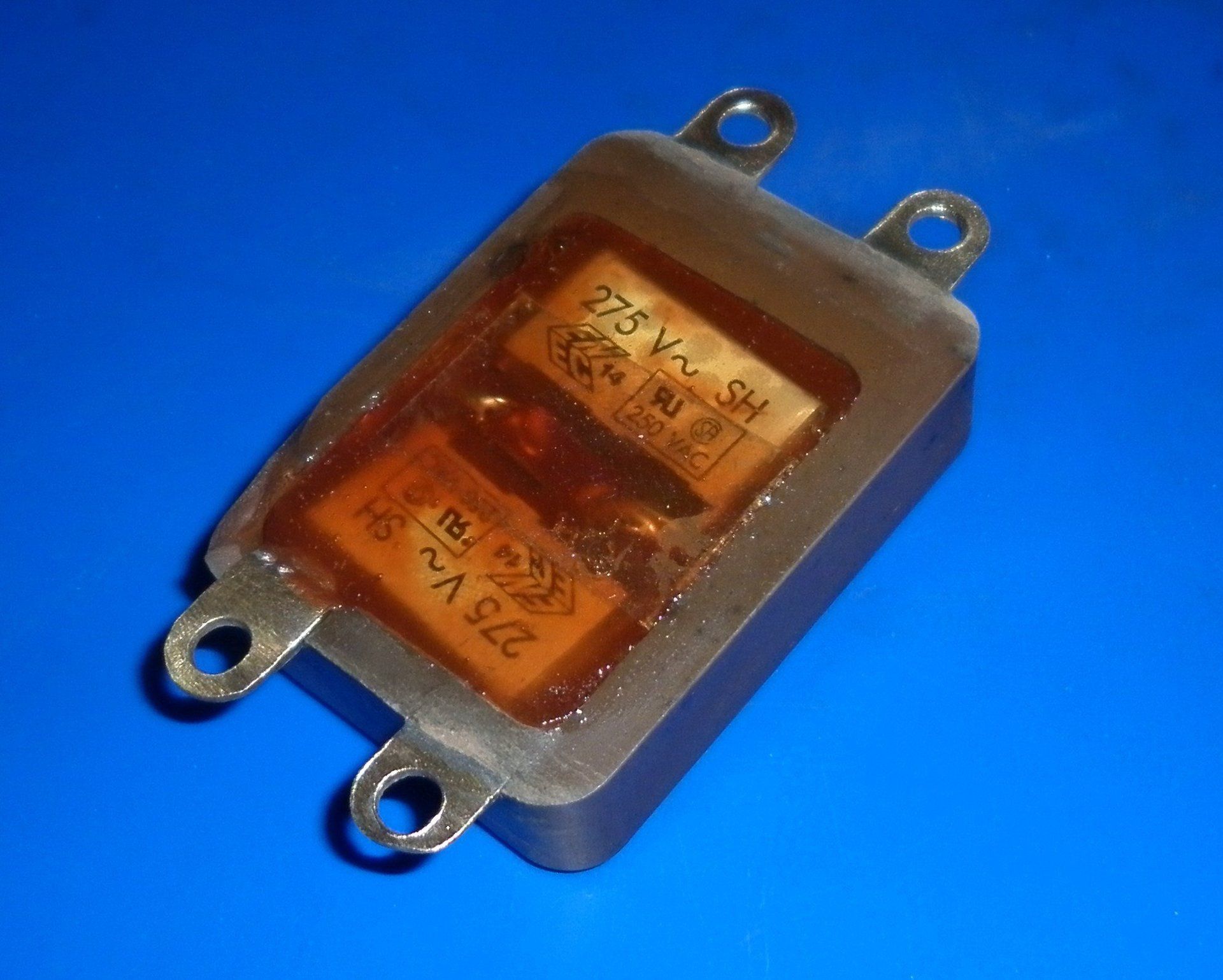
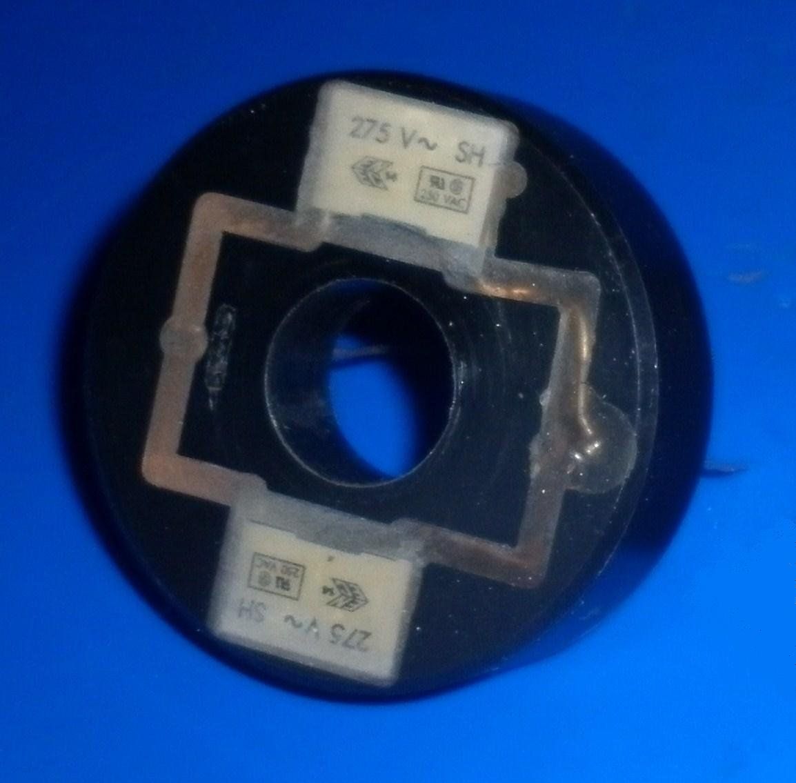
Sometimes, they are fitted into the original cases and potted.
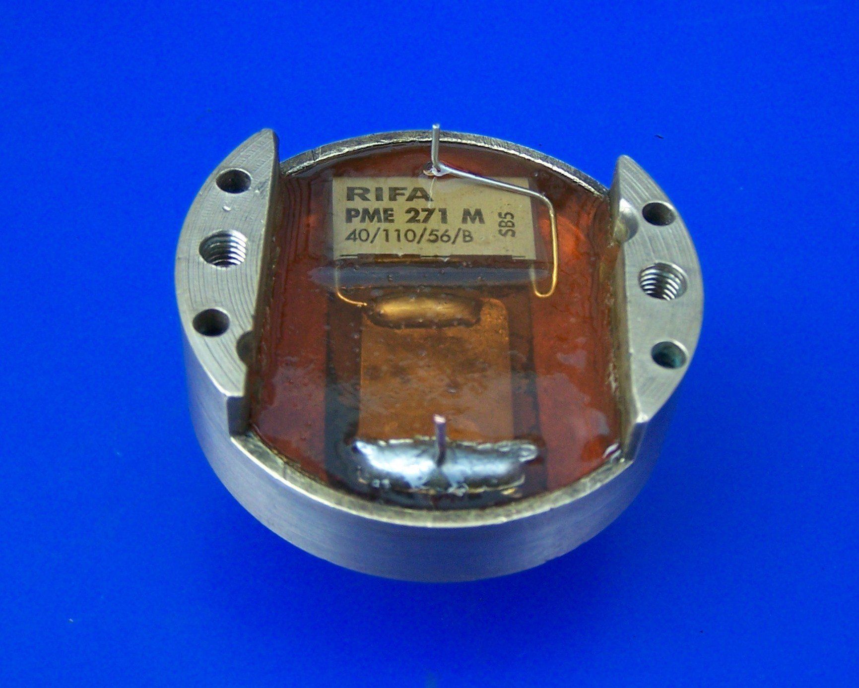
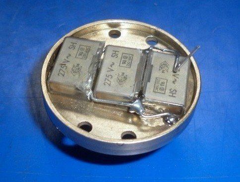
Other times they are held in place with a metal bracket, often made from a length of welding rod. In other cases an acetal housing is machined up with the new condensers then potted in place.

Note that some of these pictures show two or three capacitors used. This is because sometimes there is limited space and a number of dimensionally smaller capacitors fit better than one large one. The required total capacitance is achieved by simply wiring the capacitors in parallel and adding their individual capacitances together.
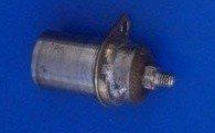
The following sequence shows how we fit the EVOX RIFA capacitor into the original body when a cylindrical can is used.
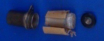
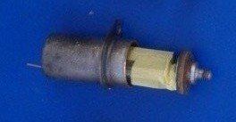
First, the original condenser has the swaged end removed in the lathe which releases the terminal and allows the insides to be pulled out.
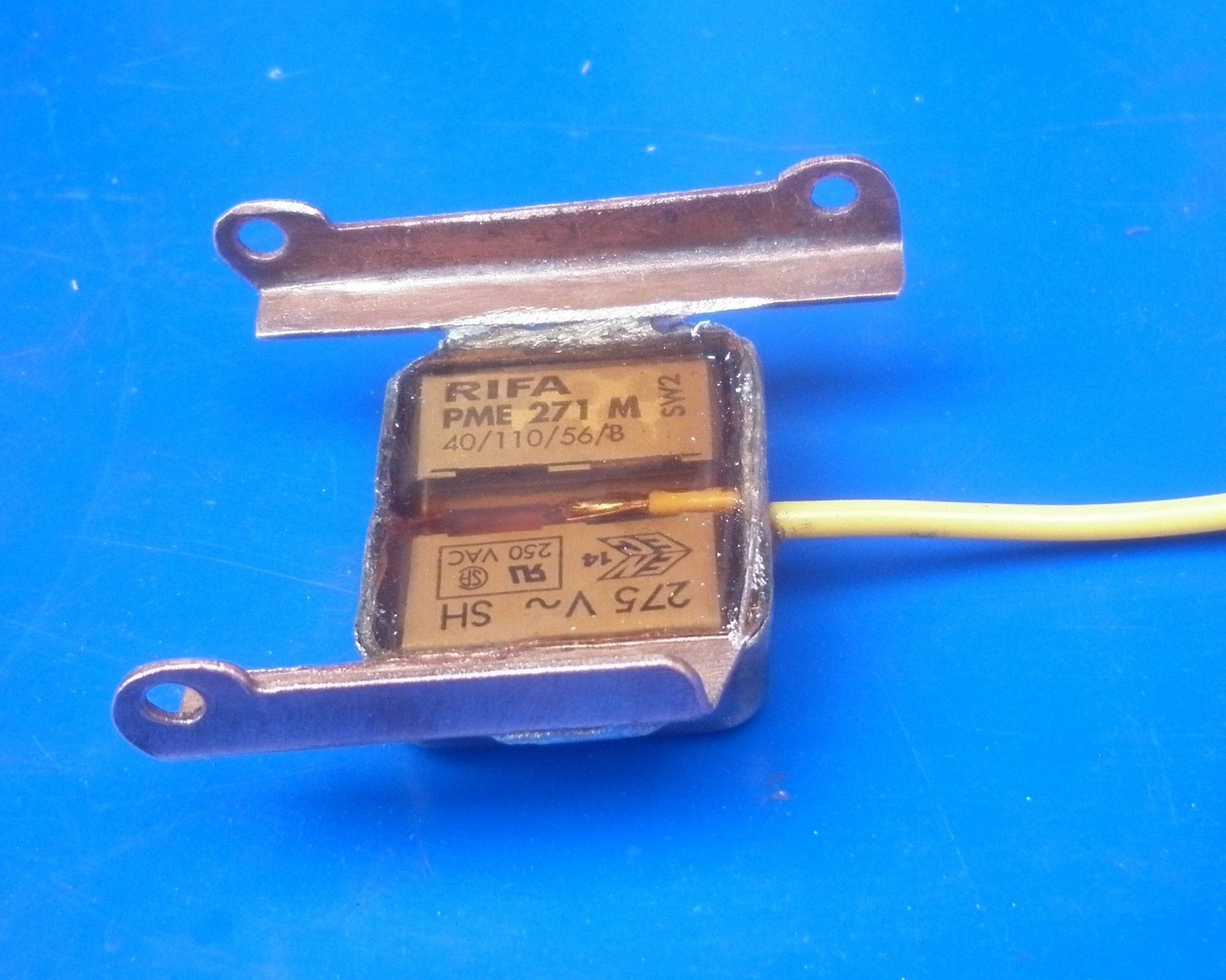
This picture shows an original EVOX RIFA on the left. Looking at the end of the condenser it is possible to see the roll of conductor/dielectric through the casing. Knowing where this is allows the corners to be removed on the linisher so that it fits inside the can. Be careful not to damage the roll!
This picture shows the terminal leads bent over and one end soldered to the underside of the original terminal.
One lead will be soldered to the can anyway but to make extra sure that the other lead doesn't make contact with the can, the EVOX RIFA is taped up using polyester tape. A small hole is drilled in the end of the can for the earth lead.
A small quantity of resin compound is mixed up and poured into the can. The EVOX RIFA is then pushed into the can so that the terminal plate is flush with the end. The resin compound usually overflows a little when this is done which serves to secure the terminal plate in place. All that remains to be done is to trim the earth lead to length, fold it over and solder to the end of the can.
The new condenser is then put through the capacitance, insulation and charge tests outlined above as a final check that the work has been successful.