Armature Tapers - theory

Armature Tapers - theory

Magnetos are always driven by the engine – it might be directly from the crankshaft (usually on two stroke engines) or from the camshaft (usually on four stroke engines). How it is driven varies as well. Sprockets and chain are probably the most common but a gear train is often used as an alternative. Another option is a toothed belt and pulleys. Sometimes the drive will include a vernier drive or an automatic advance and retard. Whatever method is used to drive the magneto will include a need to attach some form of component (referred to on this page from now on as a 'drive') to the end of the magneto’s armature. Sometimes this drive incorporates a clamp arrangement onto a parallel armature shaft but by far the most common method is to use a taper. The most common taper used is a 1 in 10 angle though others can be found, especially on very early magnetos. Even with the standardised 1 in 10 angle, the diameters come in different sizes.

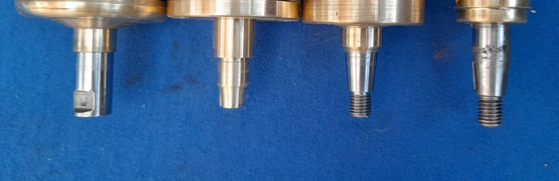
The majority of early, small magnetos used what is known as the ‘M’ taper (BTH M1, M2, for instance). Later and/or larger magnetos used the ‘K’ taper BTH KC1, Lucas K1F for instance). E and G tapers (BTH AG4, Lucas GJ4 for instance) are the largest tapers usually found and were used primarily on cars and larger vehicles. From the examples given, it can be seen that the taper letter is normally seen as part of the magneto type description, though not always. The Lucas MO1 magdyno is an obvious exception – they use the K taper! These are the most common tapers used but, as always, there are the odd exceptions to the rule! The following picture shows, from left to right, the parallel, M, K and G armature ends:

Armature tapers

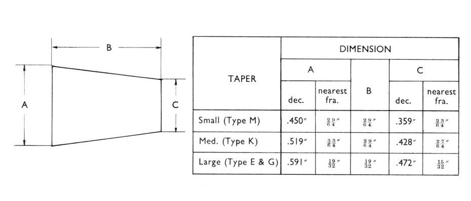
All the M, K, E and G tapers are 1 in 10 as already mentioned. The difference is in the start and finish diameters as detailed here:

Magneto taper dimensions
Many, but not all armature shaft tapers will be found with a slot for a woodruff key. It is not uncommon to find that a key is not fitted but if it is, it is there to ensure accurate location and should not be expected to take any of the drive forces. That is the job of a properly fitting taper which should be able to hold the drive on the armature shaft by itself. In fact many magneto drives do not have the corresponding keyway machined in them anyway. Once the drive is pushed onto the taper, there is always a fastener used to keep it there. The armatures with the ‘M’ taper are drilled and tapped for a 1BA bolt. The others use a threaded armature shaft to take a nut. The thread used for these nuts do vary. They are usually BSF, occasionally BSW and sometimes Metric. Oh, and sometimes they use a left hand thread! 

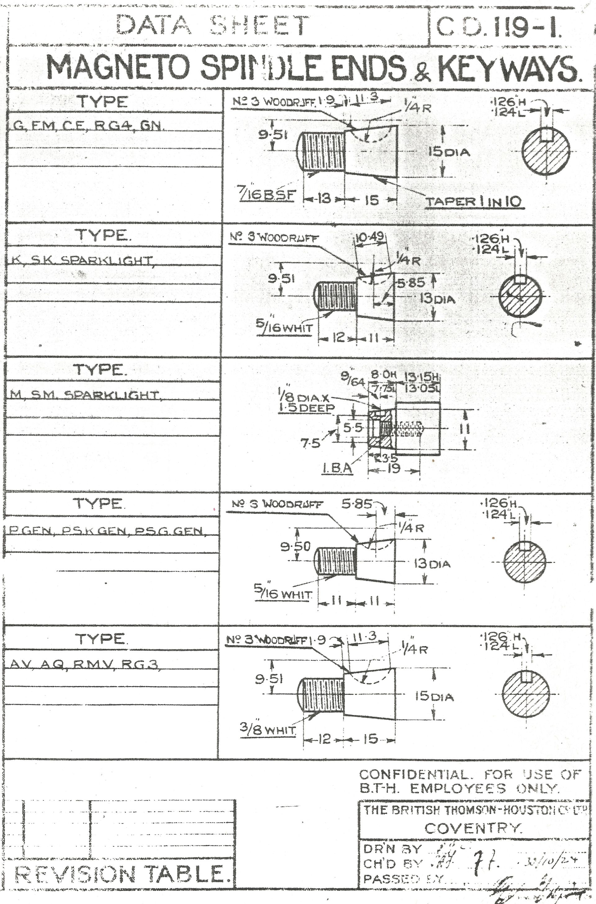
NOTE: That this BTH data sheet is dated October 1924 so is quite early. It shows the K type magnetos as using a 5/16" BSW thread. Whether this was a mistake or not is not known but In later years, the K type taper when used by BTH and many other manufacturers, was definitely 3/8" BSF!


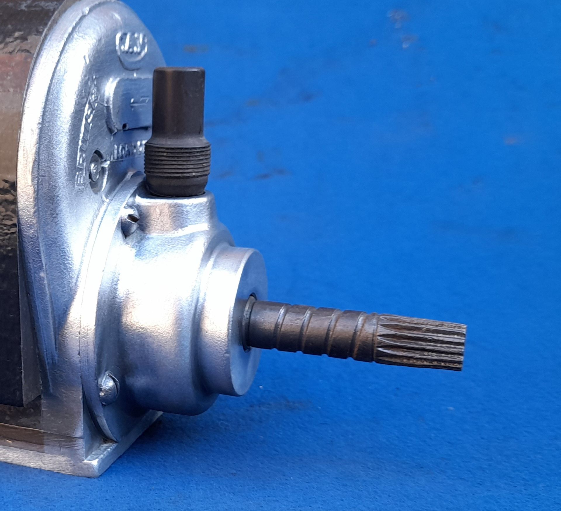
Although the tapers shown are the most common way of finishing magneto armature. There are always exceptions though - look at this CAV magneto!


There's an explanation of how to machine these tapers on the Armature Tapers - practical page in the Workshop section.


Incidentally, the same tapers are often found on dynamos too!

Share by: